If your printer’s flow rate isn’t adjusted properly, you’ll end up with wall thicknesses that don’t match up to the preview in your slicing software. The same applies to the infill. If the flow rate is too high, the infill will be more dense than projected. If it’s too low, the infill may not be enough to support the part.
The flow rate setting, also known as the extrusion multiplier, is a setting that you can adjust to determine the amount of filament to be fed through. Different filaments and materials will feed through at different rates, which is why you should fine-tune the setting according to the type of filament. The default value is either 1 or 100%, depending on the slicer.
A high flow rate will lead to excessive filament use, while a low flow rate will reduce the print quality and structural integrity.
Before we calibrate the flow rate, it’s important to calibrate the E-Steps because that’s a part of what determines the amount of filament being fed through the extruder.
3D Printer E-Step Calibration – The Easy Way!
The default E-step value for an Ender 3 is 93, but if you’ve upgraded certain parts, like switching to direct drive, you’ll need to recalibrate to avoid over or under-extrusion. Here are the steps to follow on the Ender 3.
Prime the printer
- Go into “Temperature” and then “Nozzle”
- Now heat the nozzle to the temperature you normally print at, around 210 in my case.
- After the nozzle has heated, go back into the menu and then into Motion – Move Axis – Extruder – Move 10mm
- Turn the dial to feed 100mm of filament through the nozzle 10mm at a time.
- Make sure the filament is extruding from the nozzle at an even rate.
Here’s how to do it in touchscreen mode:
- Select “Nozzle” on the main screen and press the + symbol to increase the temperature to printing temps.
- Go back to the main menu and select “Extrude” and extrude filament until you see it’s coming through even. This is to prime the nozzle before testing.
Take measurements by hand
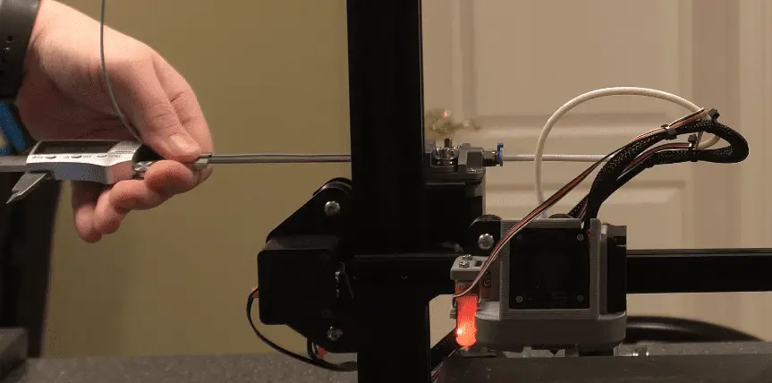
- Set your caliper to 120mm and tighten it in place.
- Put the shaft of the caliper into where the filament is feeding into the extruder.
- Pull the filament down onto the shaft to measure 120mm from the extruder. Mark the filament at 120mm with a permanent marker.
- From the menu, select Motion – Move Axis – Extruder – Extrude 10mm
- Now, the printer will attempt to pull 10mm of filament through every time you turn the dial.
- Don’t feed too much filament through at once. If you turn the dial up straight to 100mm, the gears might grind because they will try to pull too quickly.
- Once you’ve slowly fed 100mm through according to the display, it’s time to take physical measurements.
- Measure the distance from the extruder to the mark that you made previously and make a note of it, 27.02mm in my case.
- For optimal results, I like to run through the above steps two or three times before entering a new value into the E-step.
If you’re using the touchscreen mode and the extrude length automatically shows 5mm, make sure to manually set the extrusion amount again because the 5mm that it says it will do automatically is sometimes not correct. I’ve had a case where it extruded 100mm while showing 5mm on the display and I had to start the process again.
Once you have a few measurements, you can get the average of them to get a more accurate figure for calibration. Here’s my example:
(27.02 + 28.35mm + 27.93mm) / 3 = 27.76mm average.
Now let’s subtract the average length of 27.76mm from 120mm, which gives us 92.24mm. Considering we set 100mm of filament to go through on the control panel, we can now see that only 92.24% of it actually made it through. This is the definition of under-extrusion and we need to bump up the value on the E-step to correct the problem. To determine how much we need to increase the value, divide the current value of 93 with the measured average value of 92.24mm and multiply it by 100 to get a percentage.
(93 / 92.24) * 100 = 100.82 This is the new E-step value.
- In the menu, go to Configuration – Advanced Settings – Steps/mm – E-Steps/mm
- Increase or decrease the E-step value according to the result you got with your measurements.
- Go back to “Configuration” and “Store Settings” to save the values.
Here’s how to get there in touchscreen mode:
- Menu – Settings – Machine – Perimeter – Steps per mm – E
- Insert the value up to 2 decimal places. 100.82mm in my case.
I cover this in more process in this article, 3D Printer E-step Calibration (Step-by-Step Guide), and this video I made.
Factors To Consider When Calibrating Flow Rate
If you print with abrasive filaments, the nozzle could be worn, giving it a slightly larger opening. So if you have a 0.4mm nozzle, you won’t be able to get a 0.4mm wall thickness. In this case, you need to calibrate the flow rate value downwards to counteract the wider nozzle bore.
For every type of filament you use, you’ll need to calibrate the flow rate accordingly. There’s no “one size fits all” value.
How To Calibrate 3D Printer Flow Rate
Calibrating the flow rate will involve printing a test cube and measuring its walls to identify the actual flow rate compared to the flow rate value.
With a 0.4mm nozzle and a flow rate of 1 or 100%, the thickness of a single wall should be 0.4mm. If the walls are thinner than 0.4mm, the flow rate needs to be increased. If the walls are thicker than 0.4mm, you’ll need to decrease the flow rate.
This can be a tedious process if you’re adjusting the value in small increments towards the desired thickness. You may end up printing a few cubes before getting the right numbers. But I have a simple method that will only require 2 or 3 cubes to be printed.
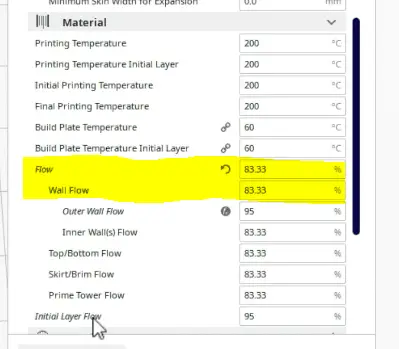
- Go into the slicer settings and verify the “flow” is 1 or 100%.
- Download this file from thingiverse.com. Test Cube
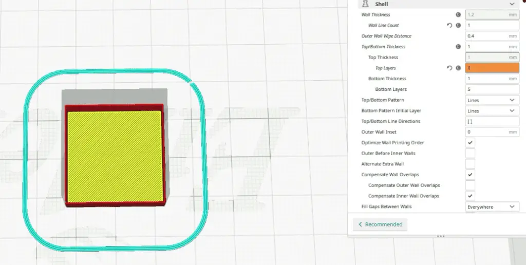
- Make sure the “wall thickness” of the test cube is the same as the nozzle diameter, 0.4mm in my case.
- Change the wall line count to 1. This should produce a 0.4mm wall on all four sides of the cube.
- Set the “infill density” and “top layers” to 0. (So that you can get the caliper in to measure the thickness)
- Print the test cube.
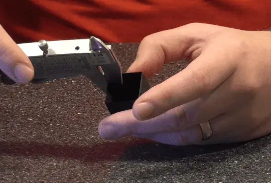
- Measure the walls with a caliper. (Calipers on amazon.com)
- Take note of the values. Mine were 4.8, 4.9, 4.8, and 4.7mm.
- Get the average thickness by adding all four sides and dividing by 4. In my case, it’s (0.48 + 0.49 + 0.48 + 0.47) / 4 = 0.48mm
- Now, divide the expected thickness by the average thickness. 0.4 / 0.48 = 0.83mm
- For Cura users, multiply the 0.83 with 100 to get a percentage value and set the flow according to the result. 83% in my case. For slicers that use a numeric value, set the flow to the result without multiplying by 100, 0.83 in this example. Either way, you’ll be reducing the flow rate by 17% to counteract the over extrusion.
When Should You Adjust The Flow Rate?
You need to increase the flow rate if the printer is under-extruding and creating gaps or other defects in the print.
If you’re experiencing over-extrusion, decrease the flow rate to avoid defects caused by extra material. Defects may include, but are not limited to, thick ribbing on the exterior, sagging material, drooping supports, and lower print resolution.
When parts come out heavier than they should be according to the specifications, you might need to decrease the flow to save on materials.
If the walls of the printed part seem weaker and thinner than spec, increase the flow rate until you get the right thickness.
These are only some of the most common reasons you would adjust the flow rate. There are many defects that can appear because of an incorrect flow, so it’s best to calibrate it according to the specific type of filament you have before starting any extensive project.
Related Articles
- 3D Printer E-step Calibration (Step-by-Step Guide)
- OctoPrint Bed Level Visualizer – Complete Setup Guide!
- Glass Bed Upgrade – Complete Guide!
- Choosing the Right Infill Percentage for the Job
- 3D Printer Printing Too Thin – Let’s Fix It!
- Quick Guide to Change the Nozzle on a 3D Printer
In Summary
You need to calibrate the flow rate in your slicer to avoid over and under-extrusion. With an accurate flow rate, you’ll be able to print parts with higher quality. The formula I give in this article helps to get closer to the exact flow value required to achieve the perfect extrusion.
Remember to calibrate the E-steps before calibrating the flow rate for better results.
Here’s a video I made to explain the flow rate calibration process.
Make sure you check out our YouTube channel, and if you would like any additional details or have any questions, please leave a comment below or join us on Discord. If you liked this article and want to read others click here.