Lights on a 3d printer are not required, they are meant to give it more of a wow effect, and NeoPixle LEDs do just that, plus more. They integrate well with the SKR Mini, and other mainboards that support them, and provide event notification using the NeoPixel LEDs. The issue that typically comes up is there isn’t much information available to help people if they run into problems, and there are a couple of critical things that need do to get them to work right.
For that reason, I put together a video, and this guide, to walk you through the entire process from start to finish. I ran into a lot of issues along the way and can now provide complete instructions.
Here is the list of steps that you will need to follow to get NeoPixel LEDs to work with your 3d printer.
- Update the Firmware
- Print the NeoPixel Housing
- Prepare the NeoPixel LED Strip
- Mount the NeoPixle Strip
- Run the Cable to the Mainboard
- Test the NeoPixel LEDs
*This guide assumes you have an SKR Mini, but most of the changes would be relevant to any mainboard that supports NeoPixel LEDs.
Step-by-Step Guide to Setting up NeoPixel LEDs on your 3D Printer
Required Tools
*Links are to Amazon and for the products I use.
- NeoPixel LEDs
- SKR Mini e3 v2.0 (Or NeoPixel compatible mainboard)
- JST Connectors (3-pin)
- Crimping Tool
- Ribbon Cable
- 380-400 Ohm resistor
- 1000uF Capacitor
- Filament
- M3 x 8mm Bolt
- M3 T Nuts
- Electric Tape
Optional Tools
*Links are to Amazon and for the products I use.
Step-by-Step Guide
Update the Firmware
The first thing we need to do is update the firmware to account for the NeoPixels. There are a couple of prereqs that are required before you can do that. I will walk through all the requirements here, but this guide assumes you have VS Code installed and have a copy of the Marlin firmware with the base configuration for your printer. If you don’t have that set up already, you should start by following the step in this video I created on compiling custom firmware for the SKR Mini.
Install GIT
The first thing we need to do is install GIT. Without it, the build will fail to pull in the necessary components and fail with an error that appears to be unrelated (I learned this the hard way).
Install Steps
- Download the installer from here
- Close VS Code if it’s open
- Launch the installer and use the default settings for every question asked
Update the Firmware Configuration Files
Next, we need to update a section in the configuration.h, configuration_adv.h, and platform.ini files.
Configuration.h Changes
You will want to search for define NEOPIXEL_LED (it should be around line 2352), and you will want to make the following changes.
| Default Setting | Updated Setting | Notes |
|---|---|---|
| //#define NEOPIXEL_LED | #define NEOPIXEL_LED | |
| #define NEOPIXEL_PIXELS 30 | #define NEOPIXEL_PIXELS 10 | The value should match the number of NeoPixel LEDs you have. |
| #define NEOPIXEL_PIN 4 | // #define NEOPIXEL_PIN 4 | You want to make sure this line is commented out unless you are overriding the default settings. The default value may be different between versions. |
| //#define NEOPIXEL_IS_SEQUENTIAL | #define NEOPIXEL_IS_SEQUENTIAL | You want to make sure you uncomment this line. The default value may be different between versions. |
| //#define NEOPIXEL_STARTUP_TEST | #define NEOPIXEL_STARTUP_TEST | This is optional, but I like to have the start test enabled. It runs through a quick test when the printer is powered on. |
Configuration_adv.h Changes
You will want to search for LED_CONTROL_MENU (it should be around line 1065) and uncomment it.
| Default Setting | Updated Setting |
|---|---|
| //#define LED_CONTROL_MENU | #define LED_CONTROL_MENU |
Platform.ini Changes
Now we need to tell platform.io to use a different NeoPixel repo. This file will be located at the root of the firmware directory. You will want to open that and search for NEOPIXEL_LED. Then make the following changes.
| Default Setting | Updated Setting | Notes |
|---|---|---|
| NEOPIXEL_LED = Adafruit NeoPixel@1.5.0 | # NEOPIXEL_LED = Adafruit NeoPixel@1.5.0 | If you already ran a build, the value may differ, but you want to comment out the NEOPIXEL_LED line. |
| NEOPIXEL_LED = https://github.com/CommandoreBombardiero/Adafruit_NeoPixel | You will want to replace the NEOPIXEL_LED line with this one. |
After you make that change, you will want to restart VS Code.
Build the Firmware
This next step is a little odd but it’s required. You will need to kick off a build that is expected to fail. That is needed to create a file that needs to be updated. In VS Code hit the checkmark in the bottom left corner to kick off the build. Then move to the step below after it fails.
Update the ___ with the Delay.h location
Now that the build has failed, we need to update the Adafruit_NeoPixel.cpp file with the location of the delay.h file. The first thing you will want to do is open the Adafruit_NeoPixel.spp file, it’s located under the \.pio\libdeps\STM32F103RC_btt_512K\Adafruit NeoPixel\ directory in the build folder. Here is an example of the full path (C:\Users\Owner\Desktop\Marlin-2.0.x-SKR-mini-E3-V2.0\.pio\libdeps\STM32F103RC_btt_512K\Adafruit NeoPixel).
Now that that’s open, you will need to search for Delay.h and update the include command with the full path to the delay.h file. The comments above it point to where it should be. In this case it’s Marlin 2.0/Marlin/Marlin/src/HAL/shared/Delay.h. Here is the full path I used ( #include “C:\Users\Owner\Desktop\Marlin-2.0.x-SKR-mini-E3-V2.0\Marlin\src\HAL\shared\Delay.h” ) note the “”, they are required. After that is updated, you can save and close the file.
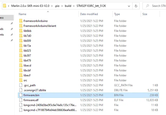
Finish Build
Next, you will want to kick the build off again, and this time it should be successful. Once the build finishes, you will want to transfer the firmware.bin file to an SD card so that we can load it on the 3d printer. The firmware.bin file would be under the \.pio\build\STM32F103RC_btt_512K directory. In my example, the file was here ( C:\Users\Owner\Desktop\Marlin-2.0.x-SKR-mini-E3-V2.0\.pio\build\STM32F103RC_btt_512K ).
Load Firmware on the Printer
Once the firmware is on the SD card, we will need to load it on the printer. This is a simple process and only takes a couple of seconds.
- Steps
- Power off the printer
- Enter the SD card with the firmware into the mainboard
- Power on the printer
- Wait about 30 seconds for it to load the firmware and restart the printer
- Remove the SD card
Print the NeoPixel Housing
The back of the NeoPixel LEDs have exposed copper, so you will need a housing to put them in. I found a design I liked on Thingiverse and modified it a bit, and created a different option with the top open if you’re looking for the LEDs to be more focused. You can download the housing from here.
You will want to choose one, or both, of these and print it. They only take a couple of hours to print, so I printed both to see which one I liked better.
If your still fine tuning your 3d printer, make sure to download the Cura profiles I use.
Prepare the NeoPixel LED Strip
Now we will need to get the NeoPixel LED strip ready to use on the printer. Here are the steps to do that.
Trim the NeoPixel Strip Down to Size
The first thing you will need to do is trip the NeoPixel strip down to size. Most of the rolls you can buy are much longer than you can use on a single printer and some come with wires already attached on one, or both, that you can use if you don’t want to solder the ribbon cable to the NeoPixel strip. You will want to make that decision now though, here is a picture of both options finished.
The NeoPixel strip I bought was 1m long, so I was able to get six strips out of it, assuming you go with strips of 10 LEDs. You will want to cut the strip between two copper connections and will want to use a sharp pair of scissors, or a razor blade, to make the cut.
*Note is that NeoPixel LEDs can be power-hungry, so if you go with more than 8-10 LEDs you may need to adjust the power source on the mainboard.
Measure Length of Ribbon Cable that will be Needed
Next, you will want to determine how long the ribbon cable should be and trim it down to size. I did this by doing a dry run with the cable. For my Ender 3 Pro, I ended up using a 28” cable, which ended up being very tight, so I would recommend going with a 30” one.
Once that ribbon cable is cut down to size, you will want to pull off a string of three wires and set the rest of them aside.
Connect Ribbon Cable to the NeoPixel Strip
Once we have the strip we plan on using, we will need to attach the ribbon cable, capacitor, and resistor to it. If you used a
If Prewired Option is Used
If you decide to go with the prewired option, you will want to cut off the 2-pin connector it has and strip about an inch of the wires connected to the NeoPixel strip and one side of the ribbon cable (If the strip has two ground wires, you will want to cut one off).
Once that is done, you will want to look at the NeoPixel stipe to make sure the input follows the direction of the arrows. If it doesn’t, you will need to move to option two.
Next, you will want to connect the 380-400 ohm resistor to the middle wire on the ribbon cable and the NeoPixel Strip. You will need to twist the wire onto the resistor leads and make sure it doesn’t come off. After that, you will want to tape any exposed metal/wire on the line (including the resistor).
Once that is done, you will want to connect the other two wires to the NeoPixel strip using the same method but don’t tape them yet. The next step is to wire in the capacitor. You will want to connect the side the has the – – – on it to the ground cable and the other side to the +5v lead.
*WARNING: Make sure the capacitor is connected correctly. If it’s backward, it can explode.
After all that is done, you will want to make a note of what color wire on the ribbon cable is attached to each feed on the NeoPixel strip, so you don’t forget. Then you will want to cover all of it up with electric tape.
If Standard Option is Used
If you decide to go with the standard option, you will need to solder on the resistor, capacitor, and ribbon cable to the NeoPixel strip. This is the way I would recommend going if you can. The end result looks better.
The first thing you want to do is solder a 380-400 ohm resistor to the middle wire on the ribbon cable and the NeoPixel strip. Once that’s done, you will want to cover the connection with heat shrink tubing.
*Note: The input must match the direction of the arrows on the NeoPixel strip. If its backwards, the lights wont work.
Once that is done, you will want to solder the other two wires to the NeoPixel strip using the same method. Make sure that when you are doing this, the solder doesn’t cross between the copper feeds on the NeoPixel strip.
After that, you will want to solder the capacitor in place. You will want to connect the side the has the – – – on it to the ground cable and the other side to the +5v lead.
Next, you will want to make a note of what color wire on the ribbon cable is attached to each feed on the NeoPixel strip, so you don’t forget. Once all the connections have been soldered in place and are secure, you will want to cover it all with heat shrink tubing.
*WARNING: Make sure the capacitor is connected correctly. If it’s backward, it can explode.
Connect 3-Pin JST Connector to the Ribbon Cable
Now we need to connect the 3-pin connector to the other side of the ribbon cable. To do this you will need to strip a couple of centimeters off the sleeve of each wire so we can connect the metal prongs to them.
After that’s done, you will want to put the metal connectors on the wire and crimp them down. The crimping process is a little tricky/awkward, so you may want to practice on a couple of test cables first.
Now we want to put the prongs in the 3-pin connector. We need to make sure the connector is wired right. Here is a diagram of how it should be wired.
Mount the NeoPixle Strip
The next step will be to mount the NeoPixel housing where you see fit. On my Ender 3 Pro, I have it mounted on the top crossbar facing down. You will want to mount the housing before putting the NeoPixel LEDs in it. I would recommend only loose-fitting both screws so the housing can slide around.
Once that is in place, you will put the NeoPixel LEDs into the housing and move it to where you want it. Once in place, you will tighten the screw that is still exposed to secure it.
Run the Cable to the Mainboard
Now that the NeoPixel LEDs are mounted, you will want to run the ribbon cable down to the mainboard and connect it. You want to make sure that you are running the cable in a way that won’t interfere with the movement of any axis. You should be able to tuck it into the slots on the frame and tape it if needed.
Here is how I ran the cable on my Ender 3 Pro.
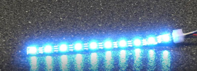
Test the NeoPixel LEDs
At this point, everything should be in place and connected, so the next step will be to test everything. When you power on the printer, you will see the lights rotate through the colors (assuming you enabled the startup test). If everything looks right, your all set.
Related Questions
What are NeoPixle LEDs?
NeoPixel LEDs are individually accessible LEDs that can be connected in a stip and controlled by a single device. In this case, it would be the 3d printer mainboard. You can typically buy them in strips of 1+ meters and can slice and connect them as needed. They are available in either RGB or RGBW, but most of them that I have seen are just RGB.
NeoPixle LEDs vs Standard LEDs
The most significant difference between LEDs and NeoPixel LEDs is that NeoPixel LEDs can be controlled individually by a single controller. This makes it possible for a 3d printer to do things like event triggers.
Lessons Learned
Print Event Triggers: The event triggers related to the actual print itself, like the color changing from blue to red as the bed and nozzle heat up, only work if printing from the SD slot on the mainboard. If you have a TFT35 and print from the USB drive or SD card on it, these event triggers won’t work.
The Resistor and Capacitor are Required: I did a test to see how things would work without them, and it was a mess. The colors were inconsistent, the event triggers skipped LEDs randomly, and the M150 command didn’t work half the time.
Final Thoughts
NeoPixels LEDs can make a great addition to any 3d printer with a mainboard that supports them. They definitely give the printer that wow effect that many people look for, especially if they do a lot of timelapse videos.
The Install process isn’t complicated, but if you are not comfortable working within VS Code and building firmware, you may be happier with an LED strip that allows you to change the colors.
Make sure you check out our YouTube channel, and if you would like any additional details or have any questions, please leave a comment below. If you liked this article and want to read others click here.
thanks for the great guide having some issues as looks like they have changed the infomation in bugfix in Platform io as cannot see the lines to change in the code?
if you know a fix? as help would be appricated.
Hi. They moved the configs to the features.ini file under the ini folder. Marlin-bugfix-2.0.x\ini\features.ini